
KAUF RGB Wall Switch
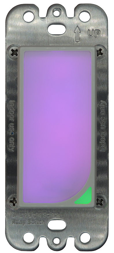
An ESP8266-based wall switch with two RGB LED lights, one big light that takes up the entire button, and a second smaller light in the bottom-right corner. The lights can be configured to turn any combination of colors when the switch turns on and off. The lights also show up in Home Assistant as light entities for control via Home Assistant. Internal automation of the lights can be disabled to allow total control via Home Assistant or other external automations.
- Two individually controllable RGB lights.
- 10A relay to switch a 100-240 VAC circuit. Relay can be configured to always on or always off.
- Large button to toggle relay or trigger automation.
- Custom firmware based on ESPHome.
- Works in Home Assistant with minimal configuration using the ESPHome native API. Includes ESPHome HTTP API for use without Home Assistant.
- Easily flashable to Tasmota and other ESP-compatible firmware.
- Requires Neutral Wire.
We recommend our GitHub readme for a description of all the configuration entities and more important information about our RGB Light Switch.
Update
If you want to update the switch through the built-in web interface, use the latest bin.gz file posted on our github releases page.
Basic Usage
This video explains some basics of how the switch works.
Adding to Home Assistant
We recommend that you import the plug into the ESPHome dashboard prior to adding to Home Assistant. See the video below under Importing to ESPHome Dashboard. You would follow the ESPHome dashboard import directions after connecting the bulb to WiFi and before adding to Home Assistant.
The following video is made for our smart plug, but adding the RGB Wall Switch is a practically identical process.
Importing to ESPHome Dashboard
Our RGB Wall Switch implements ESPHome’s dashboard import feature, so they will be automatically detected by the ESPHome dashboard. The following video explains the process.
Easy way to Control Smart Bulbs with the Switch
Hardware Information
The KAUF RGB Wall Switch includes an ESP8266 chip and uses the following pins. Each LED output is active low (inverted).
- GPIO 0 – Red LED for the small light
- GPIO 2 – Blue LED for the small light
- GPIO 4 – Blue LED for the big light
- GPIO 5 – Green LED for the big light
- GPIO 12 – Green LED for the small light
- GPIO 13 – Button input (active low)
- GPIO 14 – Red LED for the big light
- GPIO 15 – Relay output